xPlora: Light Dimming
Introduction
Did you know that the right kind of light can actually help you study better?
It’s true! Good lighting helps your brain take in information more easily, while bad lighting can slow you down and even cause eye strain, headaches, or trouble focusing.
Too dim, and your eyes work extra hard just to read.
Too bright, and the glare can make it tough to concentrate.
That’s why choosing just the right brightness is very important whether you're reading, relaxing, or getting ready for bed.
In this project, you’ll learn how to build your very own light dimmer that lets you control the brightness with a twist of a knob. Just like turning the volume up or down... but this time, it’s for light!
Let’s build a light dimmer and find the right light for your study zone!
Build the project
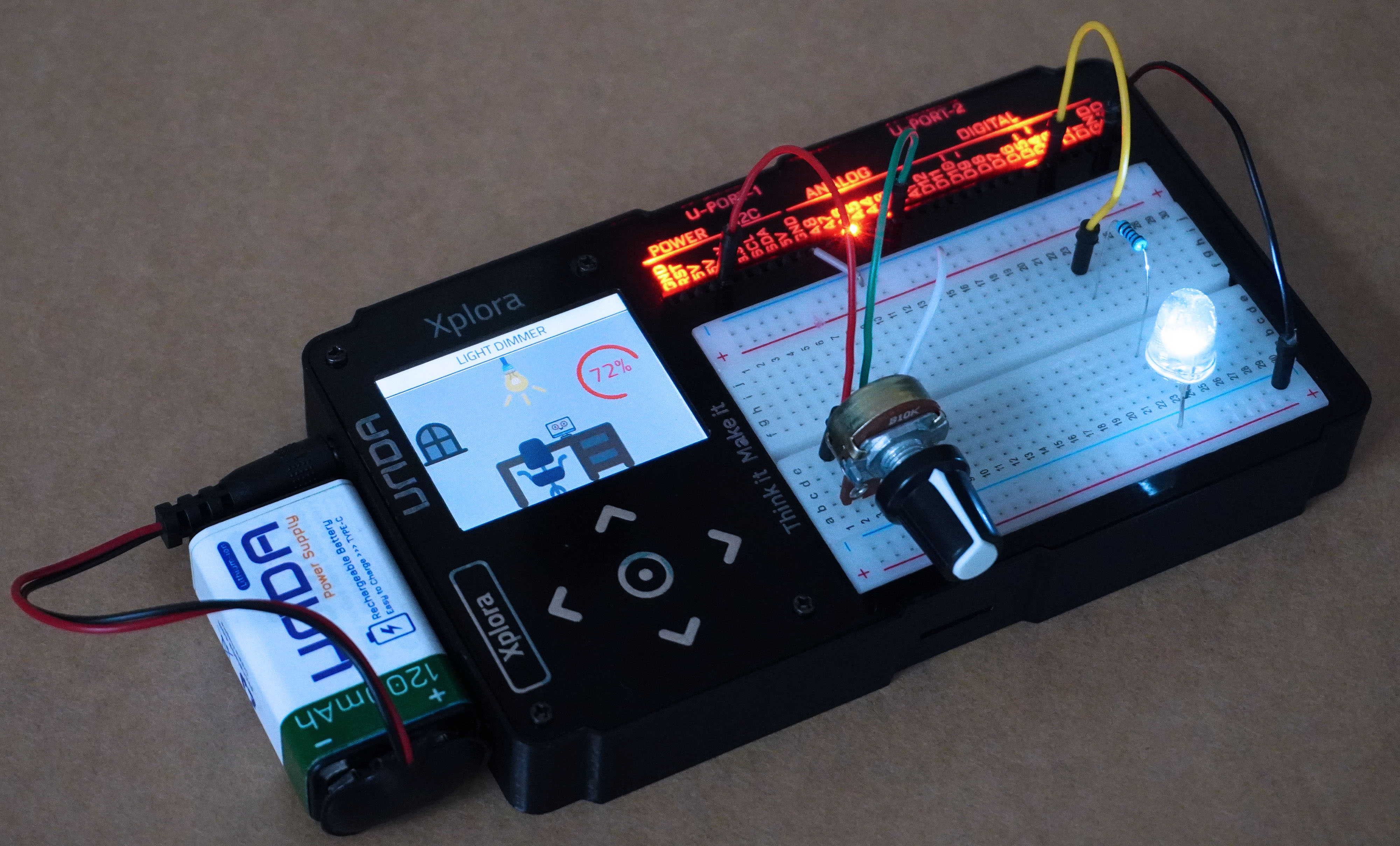
In this section we will build the Light Dimming project on the UNDA.Xplora breadboard.
Components
Below are the components needed to build this project.
| Component | Description |
|---|---|
| 1 x LED |  |
| 1 x potentiometer |  |
| 1 x resistor(220-ohm) |  |
| 3 x jumper wire |  |
| 2 x breadboarding jumper wire |  |
| 1 x battery connector |  |
| 1 x battery |  |
| 1 x Unda Xplora |  |
Step 1
Connecting the LED on the breadboard
- Step
- Build

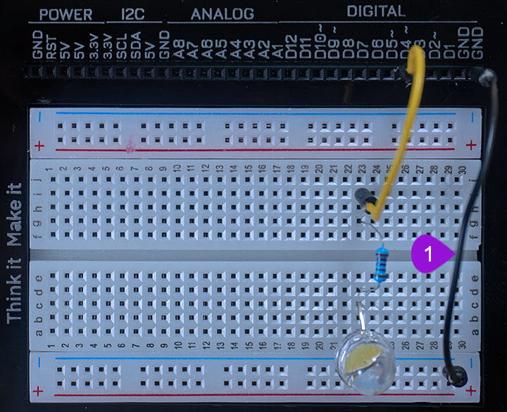
- Placing the LED: Take the white LED from your Unda Xplora Kit (You can still use any other single-colored LED). Identify the positive and negative pin of the LED; the positive pin has a longer leg than the negative pin. Place the LED on the breadboard with the negative leg of the LED placed on the negative bottom breadboard rail and the positive leg placed on the breadboard at pin c23.
- Placing the resistor: Take one 220 ohm resistor from the kit and connect it next to the positive leg of the LED from pin d23 to pin g23 of the breadboard.
- Connecting a jumper wire: Connect a jumper wire from digital pin D4 to the resistor at pin i23 of the breadboard.
Step 2
Connecting the LEDs to Ground(GND)
- Step
- Build
- Connecting to GND Pin: Take a jumper wire and plug one of its leds into GND Pin of the UNDA.Xplora Kit. Plug the other end into any pin of the bottom breadboard rail(it is marked with a blue line) to connect to the LEDS' negative pins. Recall that you can always connect from any GND Pin of the kit.
Step 3
Connecting the Potentiometer
- Step
- Build
-
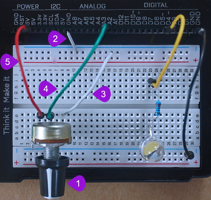
Connecting the Potentiometer: Take the potentiometer from your components casing. Place the first pin at pin b4 of the breadboard. It is important to know that the three pins are placed at equal distance from each. Therefore, when you place the first one at pin b4, automatically pin two and three will be connected to pin b6 and pin b8 respectively of the breadboard.
-
Connecting to the negative breadboard rail: Take one breadboarding jumper wire from the components casing kit (a smaller sized one will make conection easier). Connect one end of the breadboarding jumper wire to any GND pin on the kit and connect the other end to the top negative breadboard rail. You can connect to any GND pin as long as it has not already been connected to any component on the breadboard.
-
Connecting to the negative pin of the potentiometer: Using a breadboarding jumper wire (it is recommended to use a larger sized breadboarding wire), connect one end to any pin of the top negative breadboard rail and the other end of the jumper wire to breadboard pin e8 next to the third pin of the potentiometer as shown above. The third pin in this case will be the negative pin of the potentiometer.
-
Connecting to the signal pin of the potentiometer: Using a jumper wire (use any color of your choice), connect one end of the jumper wire to analog pin A3 and the other end of the jumper wire to breadboard pin e6 next to the second pin of the potentiometer as shown above. The second pin is the signal pin of the potentiometer.
-
Connecting to the positive pin of the potentiometer: Using another jumper wire of any color, connect from any 5V pin of the kit to the breadboard pin e4 next to the first pin of the potentiometer as shown above. The first pin will be the the positive pin of the potentiometer which is connected to power, in this our case power of 5V.
Run the Project
To begin running the project first connect the battery to the the battery connector and then plug it to the power port of your Unda Xplora to power it on.
Follow the steps below to load up the Light Dimming Project.
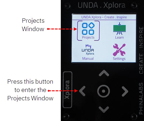
Open Project
From the main window open the projects